Overview
For these weeks, the goal was to design, mill, and solder a custom circuit board (PCB). Since my final project (the Virtual Pinball Machine) requires connecting multiple arcade buttons and an analog plunger to a computer, I decided to create a breakout board for the Raspberry Pi Pico. This board serves as the central hub, collecting all inputs and sending them via Serial/USB to the Unity game engine.
Step 1: Choosing the Microcontroller
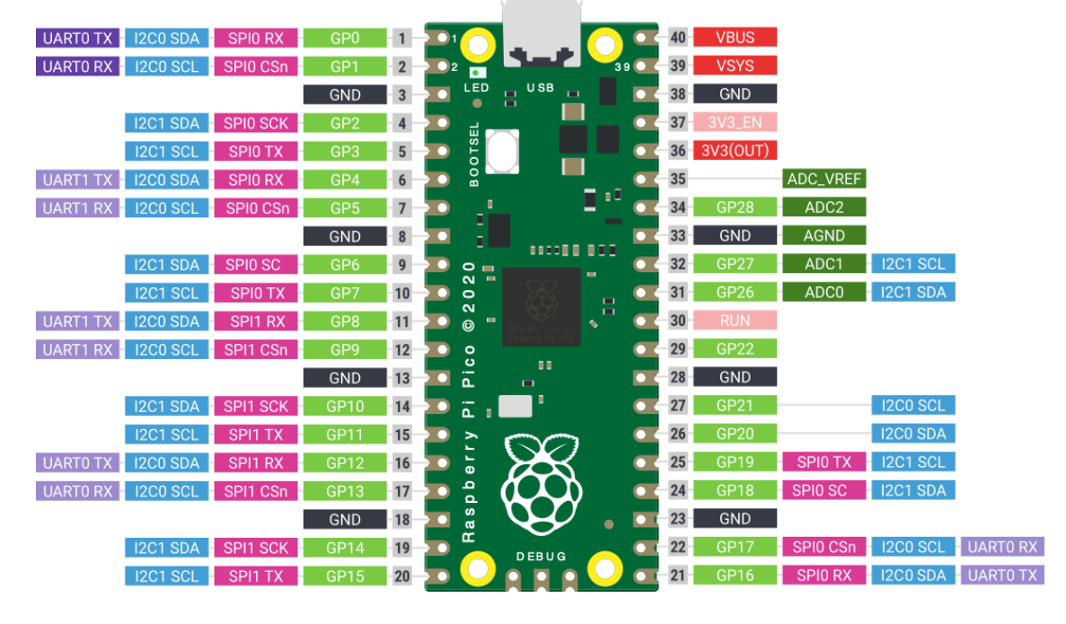
I chose the Raspberry Pi Pico because it offers a large number of digital GPIO pins (needed for the many buttons of a pinball machine) and high-quality Analog-to-Digital Converters (ADC) which are essential for reading the position of the mechanical plunger accurately. Furthermore, it supports HID and Serial communication easily, making it perfect for game controllers.
Step 2: Designing the Schematic in KiCad
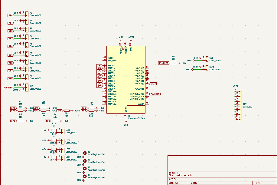
I used KiCad to design the electronics. The schematic includes:
- The Pi Pico Footprint: To mount the microcontroller.
- Input Headers: For connecting the arcade buttons (Left/Right Flipper, Start, Select, etc.).
- Analog Input: A specific connection for the plunger potentiometer.
- LED Drivers: Resistors and headers to drive the LEDs inside the arcade buttons.
I added pull-down resistors to ensure clean digital signals and prevent floating inputs when buttons are not pressed.
 Download KiCad Project
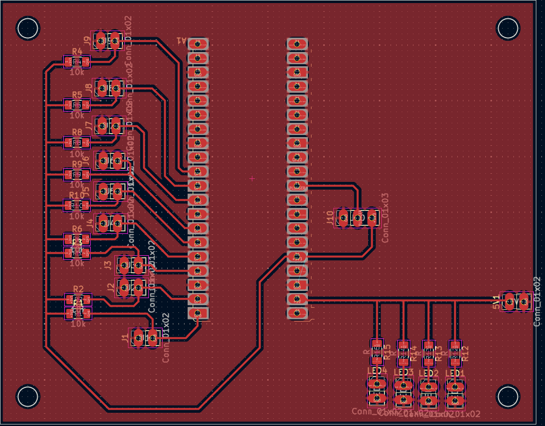
Step 3: PCB Layout and Routing
After the schematic was verified, I moved to the PCB Editor. The challenge was to route all the traces from the Pico pins to the screw terminals without using jumper wires. I used a generous trace width to ensure the milling process would go smoothly and the board would be robust. Ground planes were added to simplify the routing of the GND connections.
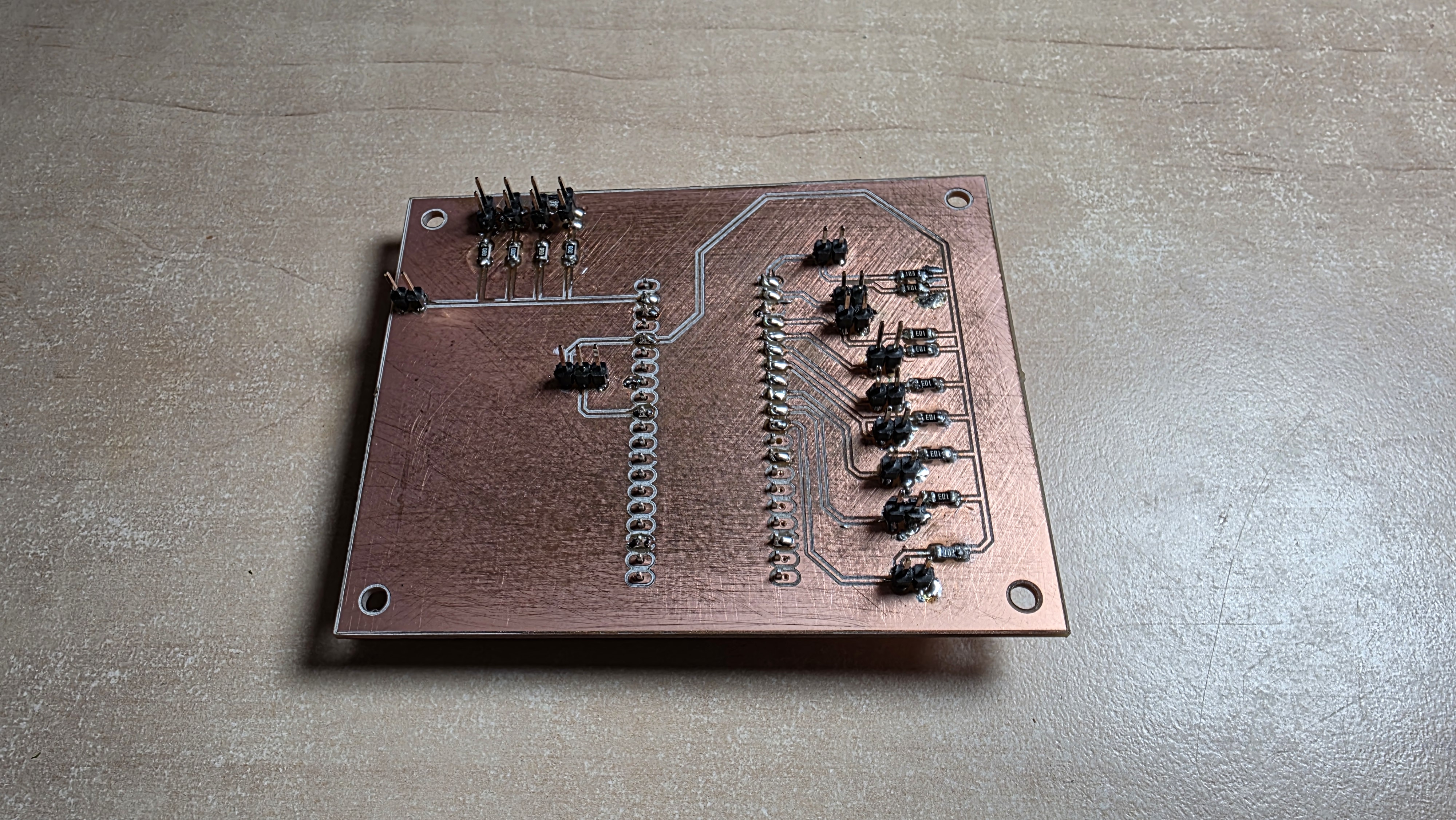
Step 4: Milling and Soldering
Once the design was ready, I exported the Gerber files and used the CNC mill to carve the traces out of a copper-clad FR1 board. After milling, I soldered the components. I used pin headers to mount the Pico (so it can be removed if needed) and screw terminals for the external button connections. The soldering process required precision, especially for the resistor arrays and the pin headers.
Step 5: Wiring and Integration
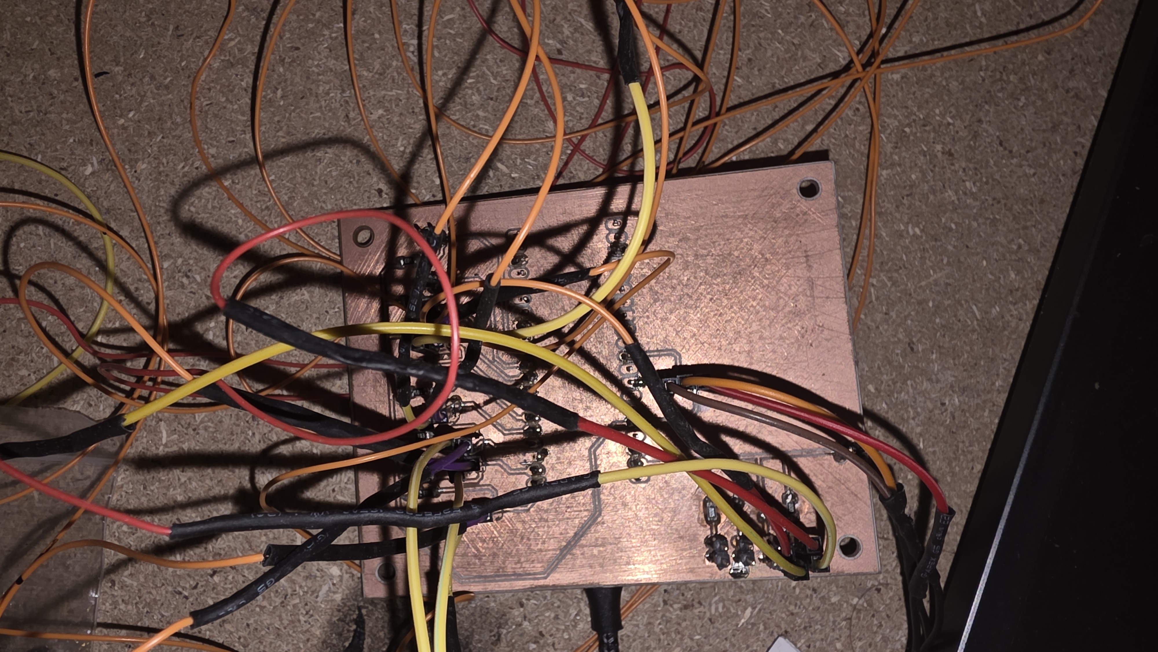
Finally, it was time to install the board into the pinball cabinet. As you can see, cable management became a real challenge. Each yellow and orange wire corresponds to a button or LED on the casing. The board successfully bridges the physical world (buttons) with the digital world (Unity), sending the keystrokes and analog values perfectly.